


Section 6 -- Actions
These are that actions we have taken, in chronological order for the most part. Some have more impact than others, and some may raise questions as to the relevance to environmental concerns.
The order of the actions does not always appear logical. Some are low hanging fruit. Others have greater logistical or disruption obstacles. Whilst Return on Investment in terms of both Carbon and Money are considered that is not the only criteria which lead to choices and actions.
The actions are individual separate projects undertaken over a number of years. They are not part of an integrated master plan of home improvement and carbon reduction together with the associated cost savings and environmental impact improvements. With a do-over, it would be planned that way, but they were separate initiatives which have coincidently coalesced into a common environmental theme.
Water Harvesting
Water Harvesting and Reed Bed
My homemade reedbed for Greywater and Rainwater harvesting
How does a reedbed help reduce the carbon used by my home? Not at all within the property. It just collects and processes bathwater and rain water. In fact it increases the carbon footprint and cost as electric pumps are involved in moving the resultant processed water. However, the significant gain is at the Water Companies' plants. Less water goes into the sewer system and therefore less energy is used to process it. We use the collected, processed, and stored, water instead of running the tap and using processed drinking water from the water mains, again thereby reducing the energy used to provide mains water.
The main reason at the time was to avoid a brown garden with significant loss of vegetation due to the impending drought, and the possibility off a similar situation in future years.

My homemade reedbed water harvesting project
| Project: | Grey water reclamation at home |
| Client: | Me / Planet Earth |
| Cost / Value: | “Undisclosed” |
| Programme: | Spring 2006 – Spring 2007 |
| Client’s Requirements: | How to beat the hosepipe ban and save the planet |
| The inspiration and research: | Article on Monday, 13 March 2006 |
Article on Monday, 13 March 2006, extracted from BBC News.
Hosepipes banned by Thames Water

Britain's biggest water company will ban hosepipes and sprinklers from next month, the firm has announced. Thames Water, whose eight million customers will be affected by the ban, says two unusually dry winters have caused "serious" water shortages. The South East has experienced its driest period for more than 80 years
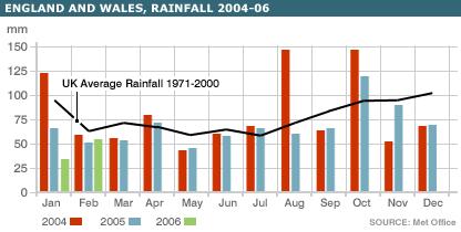
I used the water usage calculator on the BBC website and estimated that my family uses approximately 400lts of water per day. That equates to 133lts per person which compares favourably to the national average of 155lts per day. Of this about 60% is for showers and baths. However, the above calculation did not include the irrigation system that I have in the garden. I recalculated the water usage including use of a hosepipe to water the garden, but for a reduced time to account for the difference between a hose pipe and irrigation system rate of flow. This added 90 lts per day. Coincidently the water used for showers and baths equates to 80 lts per day.
We already did some water conservation by collecting rain water using a single water butt and leaving the grass to grow a little longer, and not watering it. So it seemed a simple solution to use the bath waste water to water the garden. At this point I should have just decided to have showers with the plug in and siphon out the water with a hose after it had cooled. As sane people eventually did. You can even now buy special products specifically designed to make it easier.
However, I decided to research the possibility of creating a grey water reclamation system using reed beds. The local library proved, yet again, to be a good source of information, as did the internet. I learnt,
- that different reeds deal with different pollutants and pathogens,
- about aerobic and anaerobic digestion
- micro-organisms, bacteria, fungi, and protozoa
- surface or subsurface, horizontal or vertical flow configuration
- rainfall patterns throughout the year
- rate of flow through reed beds
- and area of reed bed required per person
- Pollutants and pathogens are removed from the waste water flowing through a reed bed by a complex variety of physical, chemical and biological processes, including aerobic and anaerobic microbial activity, nitrification, plant uptake, sedimentation, precipitation and filtration.
- Reed beds are successfully and economically used in full scale black water sewage treatment and industrial effluent treatment.
Importantly reed beds require little maintenance, no additional chemicals, little or no energy dependent upon the site geography / topography and are of course, completely natural.
The Design
The Design
I wanted the system to be low maintenance and durable. It also had to be aesthetically pleasing, sustainable and capable of providing adequate clean water supplies during the increased period of drought that may be experienced due to global warming. The site is relatively flat with only a slight fall towards the top of Figure 1 ‘The Site before start’ below. To minimise the energy requirement of the system as much as possible, it had to be gravity fed. However, it ultimately had to be landscaped into the garden so some pumping was going to be necessary.
The previous research indicated the there were two basic configurations, surface and sub-surface flow, with the later being further divided into, horizontal flow and vertical flow. The sub-surface configuration is thought to be better for temperate climates, especially during winter, as the water flows through the substrate, thereby staying warmer and more efficient. To have a sub-surface vertical flow configuration would involve having outlets at the bottom of the tubs, which would necessarily involve burying pipe work, access chambers and making holes in the bottom of an otherwise water tight vessel. It would also require a relatively complex distribution system for the grey water. A sub-surface horizontal system has similar difficulties with respect to the outlet but without the inlet difficulties. I considered that the sub-surface configuration imported too much risk of failure overtime and the buried pipe work and access chambers unnecessarily complicated for the relatively small gains offered by sub-surface flow configuration compared to surface flow. The surface flow configuration has the water flow above the substrate, through the reeds, and is more similar to natural wetlands. The reduced efficiency during winter can be countered by having a larger area, together with the ability to switch to normal direct discharge into the sewers if required. Therefore the surface flow configuration was adopted.
I also considered having all of the main tubs at exactly the same level so as to provide the infinity pool type look, but decided that this was impracticable, and less attractive than gently flowing water from one tub to the next, until quietly disappearing underground.
Another significant design criteria was that the system had to be operational, at least in part, in the shortest possible time and preferably before the hose pipe ban came into force. The project was therefore done in distinct phases.
The photograph Figure 1 ‘The Site before start’ below, shows the hose pipe being put to good use, marking out the edge of the development. Several shapes and locations within the garden were considered using this technique. This is the final location but not the ultimate layout. This also represents the ‘before’ photo.
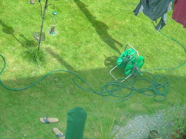 Figure 1 ‘The Site before start’
The location needed to be relatively close to the house for piping the waste water from the bathroom to the surge tank. It is necessary to have a surge tank to capture a bath full of waste water, and then to allow it to flow at a regulated speed through the system so as to allow the natural processing to take place. Consideration also had to be given for the wellbeing of the plants, such that they would not always be in the shadow of the house.
The bird feeder would have to be relocated. There would be a significant loss of grass and the washing line capacity would be reduced.
Another consideration was what to do with the excavated material. I did not want the normal hole and hill, nor did I want to have to cart the material off site. Adjacent to the site, also near the house, there is an old brick built shed.
The solution adopted was to increase the thermal mass and insulation of the shed by creating a turf wall near the shed and back filling the intervening space with the sub-soil excavated. The topsoil was stockpiled for use elsewhere in the garden. The shed wall was protected with two layers of waterproof membrane to avoid damp penetration. In turn the waterproof membrane was protected by reused expanded cardboard to reduce the risk of puncture by broken flints, primarily during construction and settlement. This additional wall also incorporated an old fashioned cistern arrangement which captures all of the rain water from the shed into open water. This overflows into the reed bed system.
It is planned that eventually the shed will also be re-roofed with a living roof. Combined this will provide a much reduced visual impact to the shed together with the benefits of a larger planted area.
The pumps necessary for irrigation circulation and to lift the reclaimed water from the sump pump chamber, the lowest part of the system, to the water storage are electric. In addition to this there is a small 12v fountain in the lowest tub, which now contains fish, and a pump to power the waterfall. Both the waterfall and the fountain are primarily for aesthetics, visual and sound, but they also provide additional aeration and agitation as a by-product. The electricity for the pumps is generally provided by two 18w photoelectric panels feeding a 12v 110Ah deep cycle leisure battery. The 12v supply from the battery is converted to the required 240v by a Sterling 600W inverter. The sump pump has to be connected to the mains to avoid the continuous use of electricity required by the standing current of the inverter if it was left on all of the time. The sump pump operates automatically by float switch which activates as soon as the sump pump chamber nears capacity and therefore requires a constant supply. The electrical requirement for the sump pump is however offset by the reduction in both the water requirement and the sewerage processing, which are intensive power consumers. Hence, despite not being fully power self sufficient, it is better than carbon neutral, it has reduced our overall carbon footprint.
The rate of flow required through the system has to be slow enough to process the water but not so slow for the water to become stagnant. It also has to be fast enough to deal with the input of grey water on a daily basis and ultimately to provide sufficient surplus to provide adequate stored water for later use. The research revealed that 1-2 square metres of reed beds are required per person to process black water but not the rate of flow through the system for grey water.
The solution was to experiment within phase one of the project.
As previously stated, pollutants and pathogens are removed from the waste water flowing through a reed bed by a complex variety of physical, chemical and biological processes, including aerobic and anaerobic microbial activity, nitrification, plant uptake, sedimentation, precipitation and filtration
The waste water treatment is outlined below;
- suspended solids settle to the bottom in still water or are filtered by the substrates and plants
- organic material is broken down by microbes that live on the roots and rhizomes
- nitrates can be taken up by the plants, or they can be transformed by denitrifying bacteria to nitrogen gas
- ammonia is transformed by bacteria to nitrates
- phosphorus precipitates with calcium, iron and aluminium compounds and is subsequently removed by sedimentation and absorption to the soil and by plant uptake
- metals and toxic chemicals are removed by oxidation, precipitation and plant uptake
- pathogens die off in inhospitable environment and are ingested by other organisms, or are killed off by antibacterial compounds.
The desktop research indicated which plants would be suitable in terms of their ability to deal with different pollutants and pathogens and to process the grey / black waste water. The environment required to carry out the water treatment outlined above could be achieved within a small site with careful design, construction and selection of plants.
Additional requirements that I wanted included, that the mixed varieties should be aesthetically pleasing, readily available, manageable, some flowering, indigenous, generally of UK origin and hardy. Such a mix of plants would inevitably have different size, spread and rates of growth. One of the listed plants is bulrushes. If they were not constrained they would quickly overrun most of the other plants. The use of separate tubs, and careful selection of which plants share tubs should eradicate this problem.
Go back to the top of this tab in this article
Go to the next tab in this article
The Design Development
Design development
The design development and phase one of construction involved commissioning one tub only and testing the plants ability to process the water.
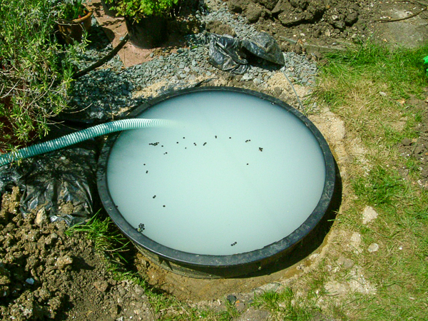 Figure 2 – ‘Phase 1 – The first filling’
The first tub, with a water capacity before planting of 370lts, was placed in the excavation on a thin bed of sharp sand. Layers of large and medium sized stones recovered from the excavation were placed into the tub followed by a bag of pea shingle. This was topped off by a layer of topsoil, previously stockpiled, as the primary growing medium for the plants. This reduced the water capacity by approximately 150lts. The waste pipe from the bath / shower was cut and a low pressure water switch installed. One arm was returned to the waste stack and the other lead to the first tub, later the surge tank. Joints and fittings were checked and the test system declared ready.
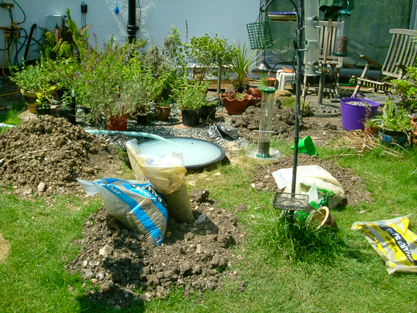 Figure 3 – ‘Phase 1 – The first filling’
Figures 2 & 3 – ‘Phase 1 – The first filling’ shows the first tub just after the first full filling. The water capacity at this stage represented bath / showers for the whole family. A mixture of reeds, flags and water hyacinth was obtained from the local garden centre and planted as show in Figure 4 – ‘Phase 1 – Planted, landscaped and operational’.
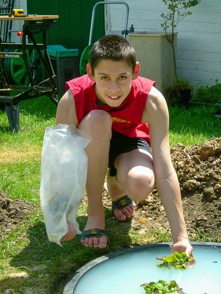
Figure 3A – ‘Phase 1 – Planting begins.
David putting in the first plants. Water hyacinth, a free-floating perennial, but not hardy.
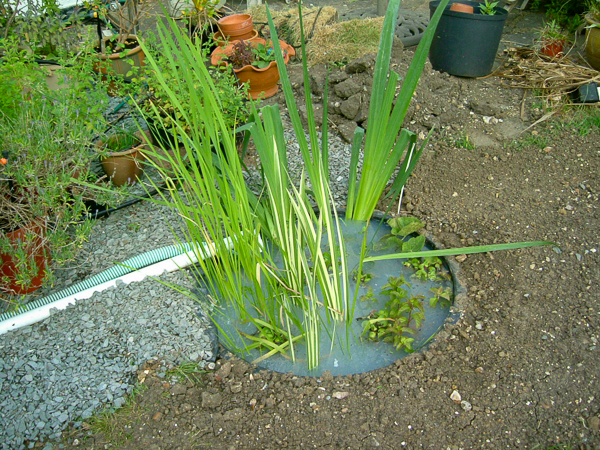 Figure 4 – ‘Phase 1 - Planted, landscaped and operational’
The density of initial planting was relatively low so as to allow for growth, and to reduce costs in plant acquisition. The suction pipe of the irrigation circulation pump can be seen lying adjacent to the white waste water pipe which supplies the tub. Grey water provided in the morning was distributed in the evening which emulated a tidal effect. The plants in the tub quickly established themselves providing daily clear water fit for irrigation. The trial was considered a success.
The stone chips of the herb bed were extended as part of the landscaping.
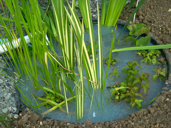 Figure 5 – ‘Phase 1 - Planted, landscaped and operational’
Grey water provided in the morning clears quickly during the day. Not totally clear but a noticeable improvement.
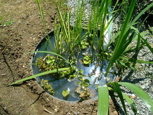 Figure 5A – ‘Phase 1 - Sun on clearing water’
Four days after first planting, grey water from the morning clears even more quickly during the day as the plants become established.
Go back to the top of this tab in this article
Go to the next tab in this article
Construction
Construction
Following the completion of the trial more tubs were procured, again from the local garden centre. I decided that three additional tubs would provide adequate capacity and an appropriate rate of flow through the system. A larger surface area final tub would provide an interim holding area and centre of focus for the subsequent landscaping.
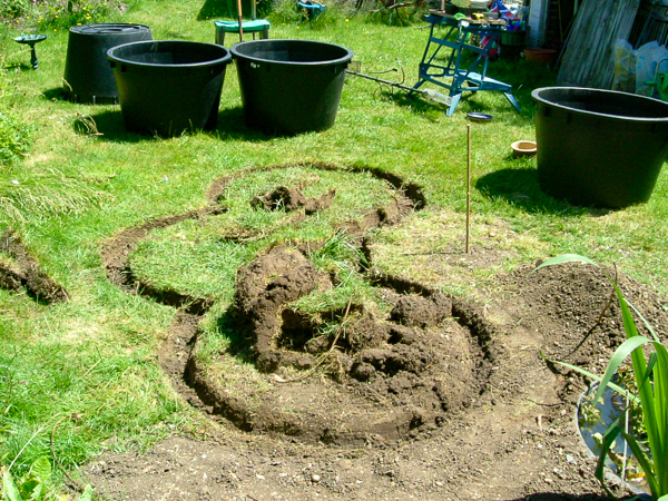
Figure 6 – ‘More tubs ready, with shapes cut in the turf around the setting-out point’
The centre of this final tub was positioned and marked with a cane which became the setting out point for the other tubs.
Then the digging in earnest could commence. By this time the hose pipe ban had been in place for some time and the ground had become rock hard. A pick axe was required even at the sub-soil level. The sub-soil layer slowly gave way to clay and chalk and then to solid hard clay.
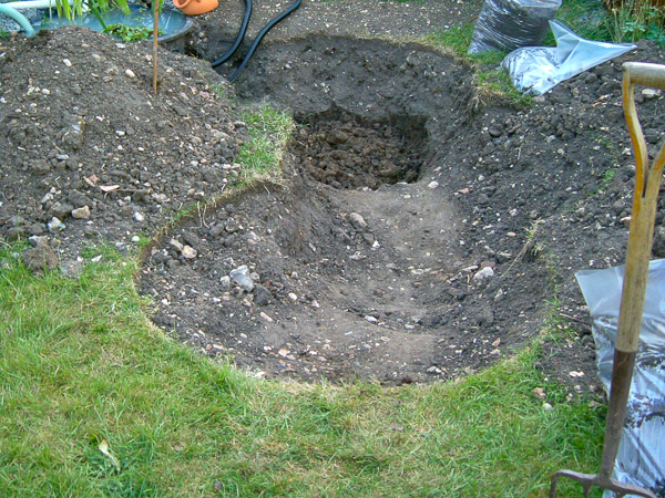 Figure 7 – ‘Holes slowly getting deeper in hard ground’
The lowest part of the dig for the final tub was just at ground water level. Any deeper and floatation problems would have had to been considered.
 The second tub has a rim height which allows the full body of water above the substrata of the first tub to flow into it. The rate of flow for the whole system is set by a simple pond hose tap on the outlet from the first tub. It can be seen as the lower outlet. The upper outlet is the overflow relief. The connection is lower than might be expected to avoid being near the rim, however the desired water height is retained by having an upside down U bend in the hose.
Each of the subsequent tubs is slightly lower that the preceding tub. A 1” pond hose is connected to the upper tub and overflows into the lower tub across the rim. This provides separation of the waters of the subsequent tubs and the slight sound of moving water.
The final tub overflows the rim into a drain channel and is collected into a sump pump chamber for later collection or distribution.
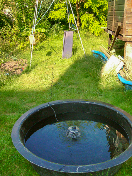
Figure 7A – Testing the solar pump with the panel propped against the swing.
Before installing the shallow lower pool I took advantage of a sunny day to test the performance of the solar powered pump. The solar panel was temporarily propped against the remnants of the climbing frame, a swing. It produced a very satisfactory flow.
Figure 7B – Satisfactory flow.
The same time as the test, and this pattern takes a lot to produce the full dome. Test passed.
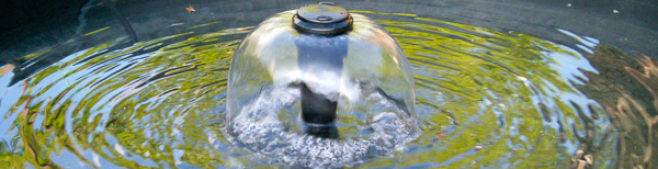
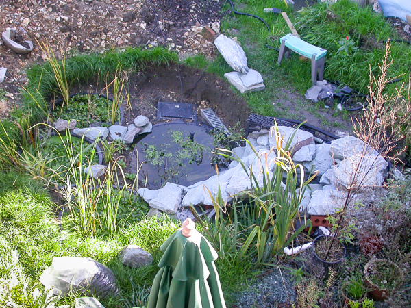 Figure 8 – ‘All tubs installed and landscaping commenced with a waterfall’
The photo shows an aerial view of the system complete and operational. The waterfall is the grey/green stones on the lower right side. it is a multi outlet waterfall with flows from the top and between the rocks.
The water hyacinths have grown remarkably well and make it difficult to see the tubs and water beneath them. The final tub can be seen more clearly with the metal cover of the drain channel showing adjacent to it. At the end of the metal cover there is the black cover of the sump pump chamber. This is in fact a 4 gallon expansion tank. This is an example of the utilisation of materials produced for different purposes being used for this project. This is the case for most of the materials other that aggregates and reeds. Sourcing some of the requirements proved to be an exercise in lateral thought and was something of a challenge.
Since then, there has been a blossoming water harvesting industry which can provide all the products needed.
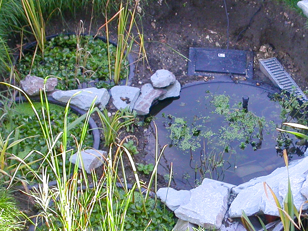
Figure 8A – ‘All tubs installed and landscaping commenced with a waterfall’
The same photo but cropped closer to see the tubs.
In the lower shallow tub, the solar fountain can be seen above the water. Also visible in the depth of the water, at the bottom of the picture is the waterfall pump. This is much more powerful and provides a impressive cascade across the adjacent stones when turned on. Neither pumps are required for the functioning of the reed beds and are only for pleasure. Visual and sound.
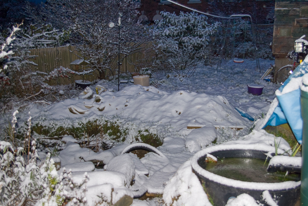 Figure 9 – ‘Winter, and early morning snowfall slows progress’
Winter set in before the landscaping was finished and effectively stopped work until spring 2007. This snow scene was an early morning in January 2007.
The water lily cistern on the right frozen over.
This proved to be beneficial. It provided sufficient time to identify two changes that I wanted to make prior to finishing the landscaping.
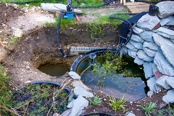
Figure 10 – ‘Redesign required, bigger pump sump dug’
The sump pump chamber needed to be enlarged to accommodate a larger sump pump. The original was a clear water submersible pump with a low clearance so as to be able to pump to within 3mm of the floor. However, even fine sediment in the sump could jam the impeller. This increased the maintenance requirements considerably, to an unacceptable level. I decided to replace the sump pump with a submersible pump which was of a different design that was capable of handling solids up to 30mm. This was therefore unlikely to get jammed by fine sediment or even small stones. Unfortunately the replacement pump was physically significantly bigger that the first, especially in height. Therefore the sump pump chamber had to be taller, deeper and bigger capacity as the second also had a higher rate of flow.
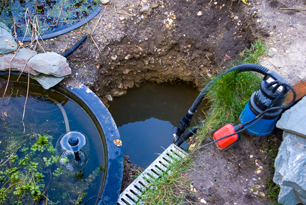
Figure 11 – ‘Redesign required, bigger pump sump dug’
At the same time as replacing the sump pump chamber I decided to add a ground source heat exchanger. It is partly experimental and partly to provide sufficient heat to the lower tub to prevent it freezing over totally, thereby allowing an ice hole so that the fish could breath. Figure 12 – ‘Ground source heat exchanger being prepared’, below shows it just prior to being lowered into the excavation. The deeper excavation for the sump pump chamber and the heat exchanger, actually a central heating radiator, meant that the heat exchanger was over 1.2 m deep and within both the summer and winter water table. The depth alone should be sufficient to not be affected by frost.
Whilst at this photo, look how clear that water is. The top tub is filled with grey / white soapy water every day, and this is the result, all of the time. The cloudy water never gets this far.
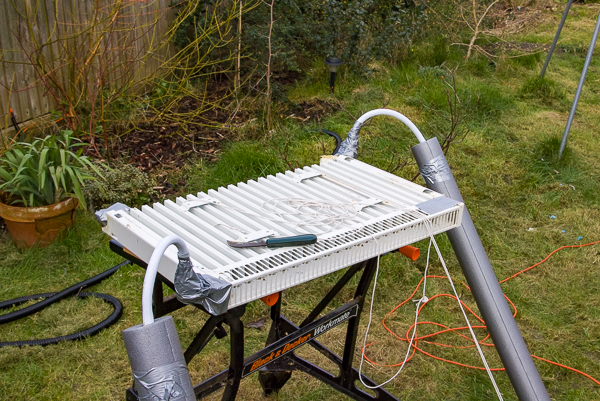
Figure 12 – ‘Ground source heat exchanger being prepared’
In this test the circulation is gravity feed. The supply pipes are insulated and the heat transporting fluid is antifreeze as opposed to water so that it does not freeze at the surface. The pipes are coiled at the lower tub water surface to provide the heating element. Provision is made in the installation to be able to check for leaks and maintain fluid levels and for a post fit circulation pump if the gravity circulation system proves to be too inefficient. If required the circulation pump will be powered by the solar battery described above. The assessment of the effectiveness of the ground source heat exchanger will have to wait until next winter.
The gaffer tape at the joints of hose to radiator is, by the way, not the fluid seal. The fluid seal is a proper plumbing watertight system with the hoses being Appliance inlet hoses. Those joints are then plastered in grease as an anti-corrosion. The gaffer tape then protects the grease and keeps it in place. Similar to the function of Denso Tape.
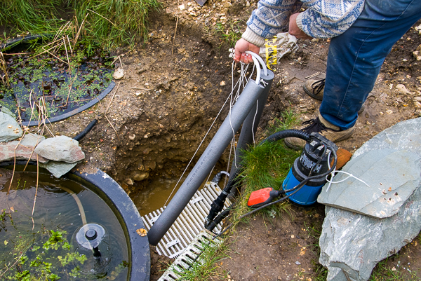 Figure 13 – ‘Ground source heat exchanger being lowered into hole’
It is lowered onto a bed of wet sand. Wet because it is just below the water table. I provides a stable foundation with good contact with the surrounding ground.
Once in place it was backfilled with more sand, ensuring all the fins were fully filled and compacted. Then water added just to make sure every crevice was filled, thereby creating a good thermal connection, at a level that would be at a fairly constant temperature.
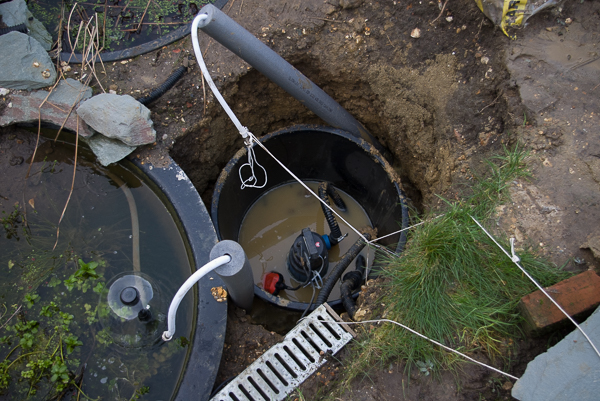 Figure 14 – ‘Ground source heat exchanger beneath pump sump’
Following some more backfill to create the level necessary for the rim of the sump pump tub to be filled by the lower tub outflow. The new sump pump tub placed in the hole with the heat exchanger insulated pipes kept clear. The new sump pump in place and connected. The red float switch positioned to bob up clear of obstructions as the tub fills.
The solar circulation pump working well.
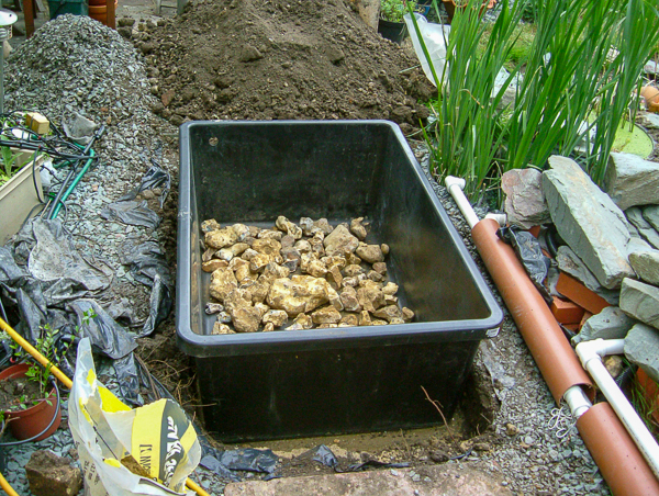 Figure 15 – ‘New Surge tank under construction - first layer’
The first design change due to operational experience was the sump pump chamber together with the ground source heat exchanger. As above. The second was to enlarge the surge tank to provide greater capacity before overflowing. the existing surge tub was retained, but was no longer the surge tank. The only available position, considering both elevation and plan, was the herb bed. Fortunately, they were all in pots on a bed of green stone chippings, so it was not difficult to move them.
The plumbing had to be altered as well. The 40mm waste pipe run was raised and inserted within a 150mm drain pipe as a service duct or conduit. This new arrangement would also require the construction of a bridge or ramp in the area of the water lily cistern. The new garden path.
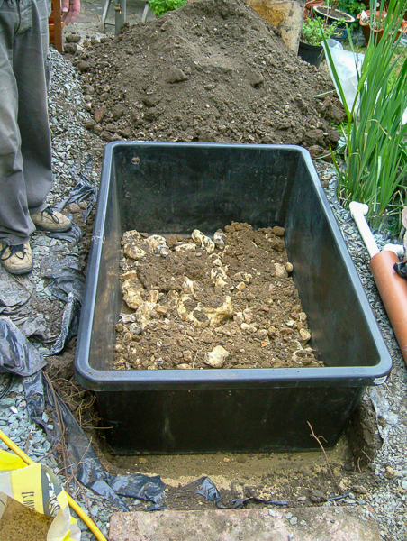
Figure 16 – ‘New Surge tank under construction - second layer’
The first layer of large stones salvaged from the big dig the previous year, together with the second layer of subsoil provide a firm anchor for the plants roots. This also helped achieve the no export of materials off site. Slightly smaller stones were bagged up and used to create retaining walls.
The distinct layers could perhaps aid the aerobic and anaerobic digestion even in the relatively short time the grey water was in the surge tank before commencing its journey through the red beds below.
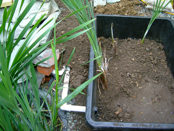
Figure 17 – ‘New Surge tank under construction - third layer (topsoil) and first planting’
Viewed from the other end, this is the moment that the feeder pipe was turned from out pouring over the lip of the existing surge tub, on the left, and into the side of the new surge tank on the right.
This also means that whilst previously the feeder pipe fully drained, it is now permanently wet. Waiting for the next bath of water to push the previous residual water through. Gurgling and bubbling as the surge tank fills above the inlet.
Just three common Bulrushes in this photo. It did not take long to fill the tank with plants, and for them to consistently grow to over 8ft high, about 2.4m.
Go back to the top of this tab in this article
Go to the next tab in this article
Planting and Landscaping
Planting and landscaping
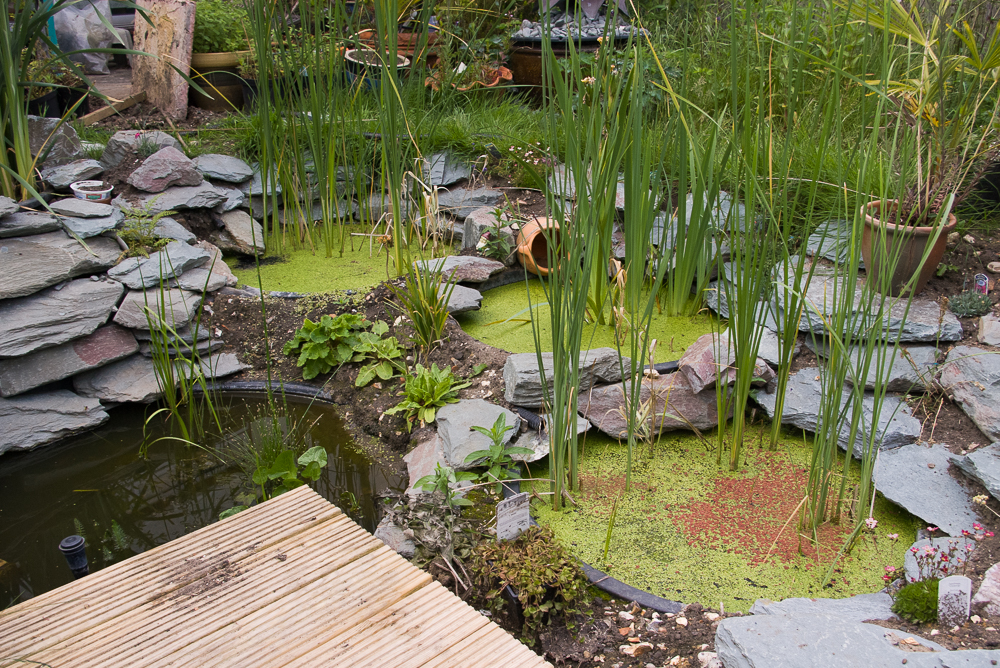
Figure 18 – ‘Landscaping nearing completion, viewed from the pier side’
The hard landscaping is procured locally but unfortunately sourced from the lake district. A case of aesthetics over green. The rocks are 1 tonne of Lakeland Green rockery and 1 tonne of Lakeland Green stone walling. So maybe it is green after all.
The pier is decking, just large enough to place a deck chair on, and do some fishing? It is actually the cover for the sump pump chamber and is easily removable for maintenance.
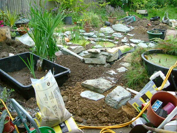
Figure 19 – ‘Landscaping nearing completion, viewed from the house side’
Figure 18 – ‘Landscaping nearing completion, viewed from the pier side’, above, and, Figure 19 – ‘Landscaping nearing completion, viewed from the house side’, right, shows the aquatic planting complete.
The new raised footpath allowing the pipes to pass beneath as well as the cables for the pumps. The water lily cistern on the right shows the new overflow in 40mm waste pipe. Again using the inverted U, and in this case fallen over as well. The water comes out of the cistern away from the rim construction, but cannot flow away until the water both within the cistern and in the pipe reach the bottom of the upper elbow joint. The more the excess, the more the flow, thereby a good overflow whilst still maintaining water height in the cistern. The cistern is feed from the adjacent shed roof, so can be susceptible to storms. It is therefore just rainwater that would be overflowing, and accordingly skips the surge tank and outflows directly into the lower system.
As previously stated, different reeds deal with different pollutants and pathogens. Certain plants, such as common reeds (Phragmites australis) and cattails (Typha spp.), have hollow stems that can transport air to the roots, supplying microbes with additional oxygen. Some take up specific metals or chemicals, other produce an exudate that kills pathogens.
Some of the plants in the system are listed below together with their ‘special abilities’.
- Common reeds (Phragmites australis) and Cattails (Typha spp.)
- flocculate colloids, eliminate pathogens
- Bulrushes (Schoenoplectus spp.)
- take up copper, cobalt, nickel, manganese, chlorinated hydrocarbons
- eliminate pathogens
- exude antibodies
- Grasses (Scirpus spp.)
- break down phenols
- eliminate pathogens
- Rushes (Juncus spp.)
- treat chlorinated hydrocarbons, cyanide compounds, phenols
- remove pathogens
- Yellow Flag (Iris pseudacorus)
- Remove pathogens
The water treatment provided by the above plants is supplemented by floating aquatic plants such as Water Hyacinth and Duckweed. Unfortunately Water Hyacinths are not hardy. However, they can be readily replaced with a few plants from the garden centre during spring. They are very prolific and will soon cover the tubs again. Alternatively a few plants could be over wintered in a frost free environment. Duckweeds are one of the smallest flowering plants and have one of the fastest reproduction rates.
- Water Hyacinths (Eichornia crassipes) and Duckweeds (Lemna, Spirodela and Wolffia)
- Take up nitrogen and phosphorus
- Microbes living on roots transform nitrogen to ammonia
- Take up trace metals, Boron, Copper, Iron, Manganese, Lead, Cadmium, Chromium Arsenic
The grey water from the bath / shower flows through this assortment of plants to produce crystal clear water.
The final planting is alpines and herbs in amongst the rocks, producing the desired ultimate effect of a small water treatment plant fully integrated into a garden environment.
The finished product, albeit with some site tidying still to do.
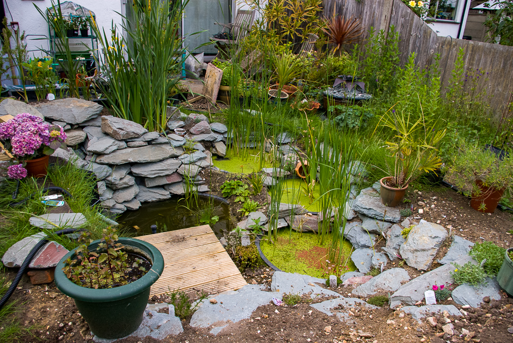
Figure 20 – ‘Landscaping and additional planting complete, viewed from the pier side’
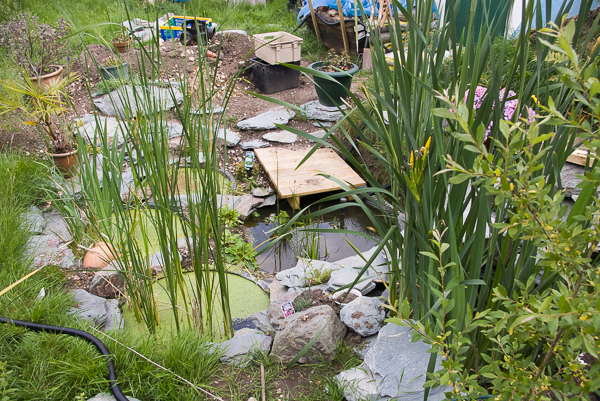
Figure 21 – ‘Landscaping and additional planting complete, viewed from above’
These photographs show the finished, commissioned, and operational system. Just the site tidy up to finish the project.
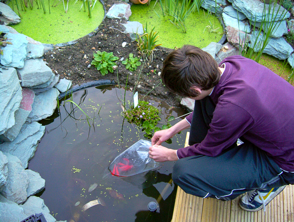
Figure 22 – ‘David preparing to release fish.’
In this bag there are some ordinary goldfish. Another bag contained Golden Orfe. The final offering, Golden Tench. Green Tench were also considered, but discounted in favor of the Golden variety due to a better chance of seeing the bottom feeders with a gold coat on. However, the Golden Orfe were a mistake. Whilst they shoaled well with the goldfish and made the pool quite active, as soon as they became somewhat larger they became prone to jump, not always landing back in the right body of water, or indeed, any water. They were not replaced.
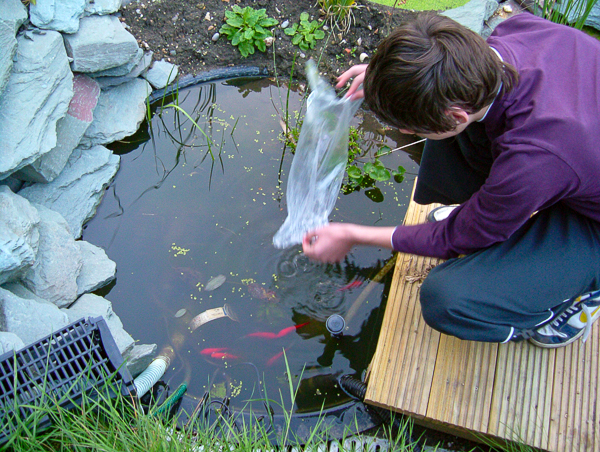
Figure 22A – ‘David preparing to release fish.’
The goldfish in their new home. Going for an initial explore.
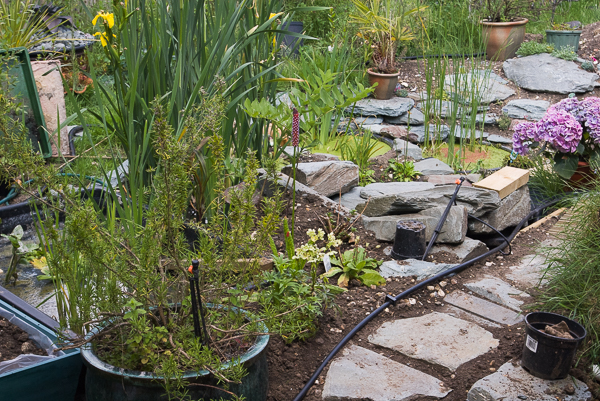 Figure 23 – ‘Landscaping and additional planting complete, viewed from the house side’
Rosemary in a green ceramic pot. Hostas and other shade loving plants in wooden troughs beside the surge tank. Automatic irrigation in place. Hellebores and primrose in the verge. Piece of wood providing the sloping escape for animals that find themselves trapped in the surge tank. Turf wall fronting the water lily cistern.
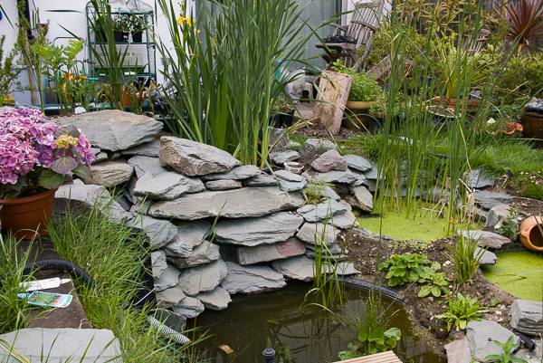
Figure 24 – ‘The waterfall’
The waterfall is purely for aesthetics, and is not necessary for the aeration of the system. It is not the equivalent of the rotating sprinkler bar at the sewage works.
It is fed entirely by the waterfall pump submersed in the lower tub, which is where the water returns directly to, not via any other part of the system. The flows it would create are far to large for the reed beds. It feeds multiple outlets. The top one opening into a small pool before disappearing into the rocks again. Another is more of a spout out of the rock face. A lower one adds to the flow from the top one to create a wide flowing cascade. There are several nooks, crannies, cavities, and caverns, built into the depth of the water fall primarily to provide winter homes, and hiding places, but also to provide a degree of variation to the water flow.
The pump is only turned on when we are in the garden relaxing. It is not on in this photo.
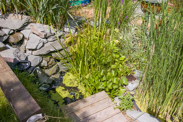
Figure 24A – ‘The waterfall’ One year on.
One year later and you can see the amount of growth and naturalisation. It is a warm sunny day and the pump is turned on. Dry rocks and wet ones. Cascading water bubbling down into the lower pool.
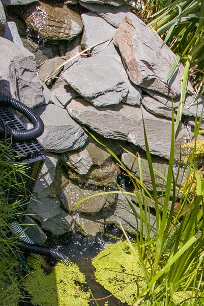
Figure 24B – ‘The waterfall’ One year on.
Slightly closer view. The cascade stream in the middle and a spout on the right edge of the photo.
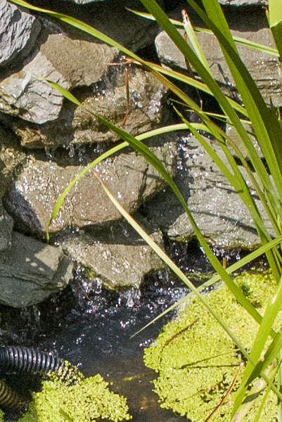
Figure 24C – ‘The waterfall’ One year on.
Closer again, water streaming down the rocks and falling into the lower pond below.
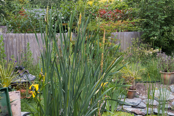 Figure 25 – ‘Bulrushes in the primary surge tank’
The surge tank has to be large enough to accommodate all the family having baths / showers in succession and to allow for the increased density of plants envisaged in future years. The plants and their roots and rhizomes, as they grow, significantly reduce the available volume for waste water.
Go back to the top of this tab in this article
Go to the next tab in this article
Wildlife
Wildlife
Earlier this year, just in one tub, covered in duckweed, nine frogs were counted. Newts have also colonized the system.
The photographs below are just an indication of the wildlife that resides in or visits. Wait for the photos to auto slide, or click the arrows near the edge of the photo, the dots, or the thumbnails at the bottom.


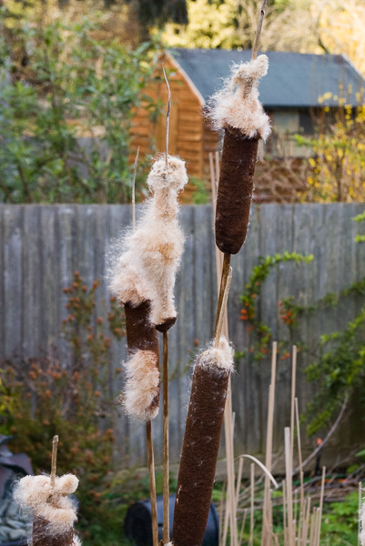 Figure 36 – ‘Bulrushes (Typha latifolia) in spring’
 Figure 37 – ‘Bulrushes (Typha latifolia) in spring’
Go back to the top of this tab in this article
Go to the next tab in this article
Storage
Storage
The excess water reclaimed needs to be stored and there needs to be a reserve of stored water in times of drought and / or hot weather to supplement the daily production of reclaimed water. At the start of this paper it was established that I needed approximately 90 lts a day to irrigate the garden at the same intensity as previously done. If I required to store adequate water for just half a year’s supply I would have to produce and store in excess of 16,000 lts of water. This would be a huge container. However, when consideration is given to the rainfall pattern in Southern England the storage requirement is significantly reduced. If I were only relying on rainfall as my supply of usable water I would have to provide storage for 1,700 lts. This would be amassed over winter and alternately used and partially replenished during summer. With typical rainfall patterns the reserve of water would be almost depleted by the end of summer, relying on autumn rains to cope with an India Summer. However, as this cycle is supplemented by the reclamation process I have decided to limit my storage ability to 800 lts. This is provided by a cluster of four domestic water butts linked together. Other storage options considered included, a pond, a reused orange juice container, of the shipping variety – 1,700 lts or an ISO liquid container – 1,000 lts.
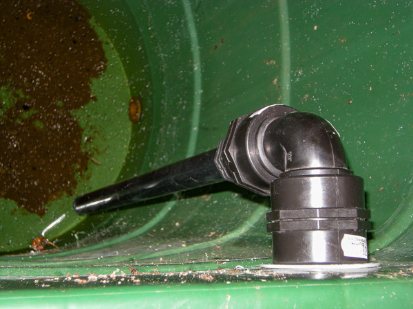
Figure 38A – ‘Storage with feed pipe’
The first of the four linked domestic water butts, with a downpipe for the water arriving from the sump pump at the end of the reed beds.
The remaining water butts are all interconnected at low level, so all the water butts have the same level of water.
The sump pump fills the water butts and the irrigation pump draws water as required. If there is excess water it will overflow into a small area of native trees planted at the bottom of the garden. The amount of excess water is not expected to be as large as may be expected by calculation of requirements against bath / shower water usage. The reclamation process has inevitable losses. The aquatic plants have a high water take up. Surface water evaporation is significant in hot weather. Some of the water loss is designed into the system by providing direct systems of water draw into areas adjacent to the tubs to provide continuously damp areas for moisture loving plants, so as to enhance the natural look of the system.
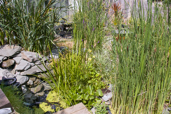
Figure 39A – ‘The planting filling out’ One year on.
Go back to the top of this tab in this article
The end of this set of tabs in this article, continue reading below.
Conclusion
In conclusion this has been a very rewarding project involving a number of different ‘green’ techniques to provide a solution to a specific problem. Albeit that this problem has yet to occur this year, the system is still working very well, producing crystal clear water day after day, whatever the weather. I have not had the water tested to be able to categorically state its quality, but suspect that it is actually potable. I believe that it has significantly reduced the family’s carbon footprint and provided interest and ongoing enjoyment.
I have added two narrow water butts at the front of the house to capture rainfall from those elevations. The water butts are small and relatively unobtrusive. It is however sufficient to be a surge tank and to accommodate the build-up during downpours which is free to flow via a garden hosepipe to the reed beds in the back garden, after keeping back enough in the second tub to water the pots in the front garden. The rain water flush provide by the front water butt and the brick shed cistern also reduce the systems maintenance requirement.
Another development to be considered is the adaptation of the WC supply to be both mains and reclaimed water. This would further reduce our mains water consumption.
Finally my thanks to the books and internet articles that provided the invaluable reference material that made this project possible.
Updates
June 2010
August 2020
- Transfer from old site to this one
- Photos re-mastered
- Some additional photos, Figure numbers with sufix.
- Minor text corrections
December 2021
- Added tabs to aid reading
- Incorporated this article inside another
Go back to the top of this tab in this section
Go to the next tab in this section
Natural Swimming Pools/Ponds
Natural Swimming Pools/Ponds
If only we had the space!
Natural Swimming Pools/Ponds
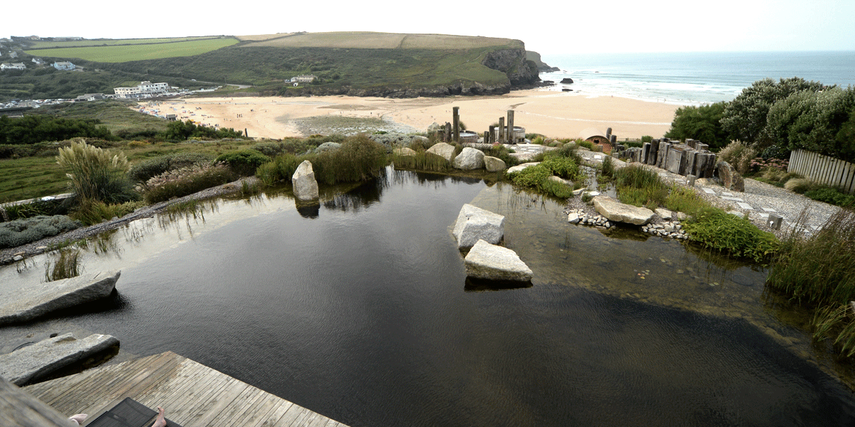
Moving on from my homemade readbed project, not only has an industry emerged catering to Water Harvesting, which is a lot less Heath Robinson than my early attempt, there is also a resurgence in wild swimming. See history of wild swimming. Even the BBC broadcast about wild swimming in one of Kate Humble's programmes, 'Off the beaten track'. Unfortunately Iplayer does not have the programme but here are some clips. Kate with Natasha Brooks, explain why. Kate enters the water. Thermals back on.
A very different view of wild water with Kate Silverton.
We were holidaying in the area and found ourselves at Carding Mill Valley Reservoir just as somebody was going for a swim. The signs allow swimming but not on your own. It was evident that she was a regular.
One length done and we don't feel the need to stay for safety's sake, and leave her to her swim.
It looks a beautiful place to swim, very peaceful and quite, with just the bird song. Proper communing with nature.
Some of the comments on Wild Swimming website for this location even suggest skinny dipping is OK.
However, is is eventently cold.
She was careful getting into the water and took it very slowly. Coping with the cold water shock. On the way back down the track, as she overtook us, she was well wrapped up in one of those full length quilted coats. Very cosy, but still looking cold.
However, as beautiful as those spots are, why travel all that way to find seclusion or to take those risks when you can do something closer to home. Well, at home, if you have a large enough garden. and do some water harvesting at the same time.
David Pagan Butler shows how he built his pools.
Another of his, but for somebody else this time.
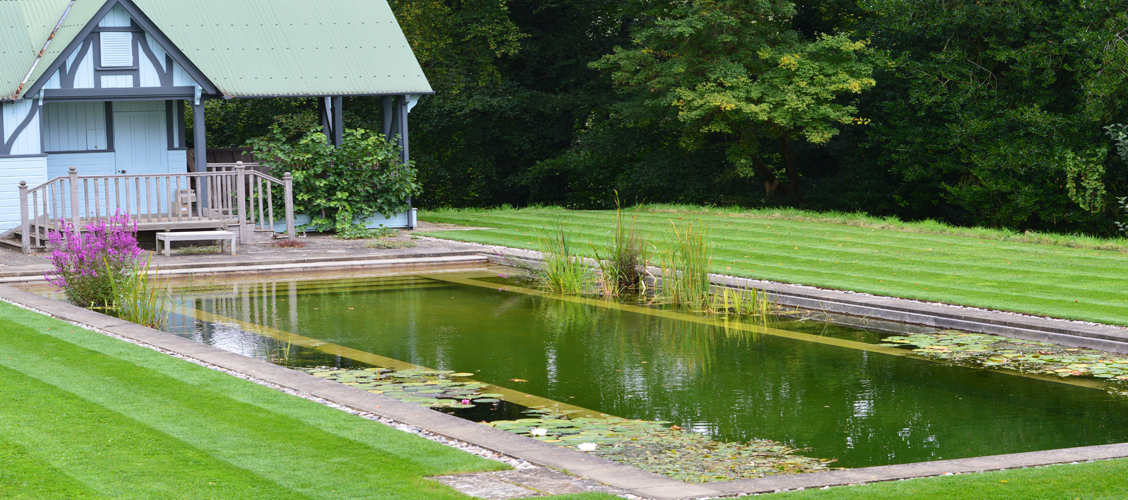
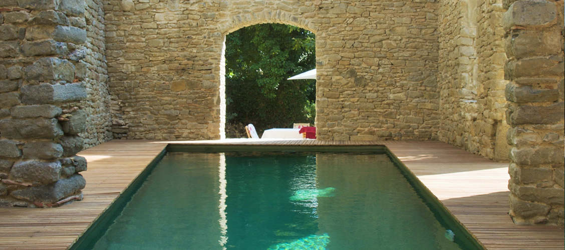
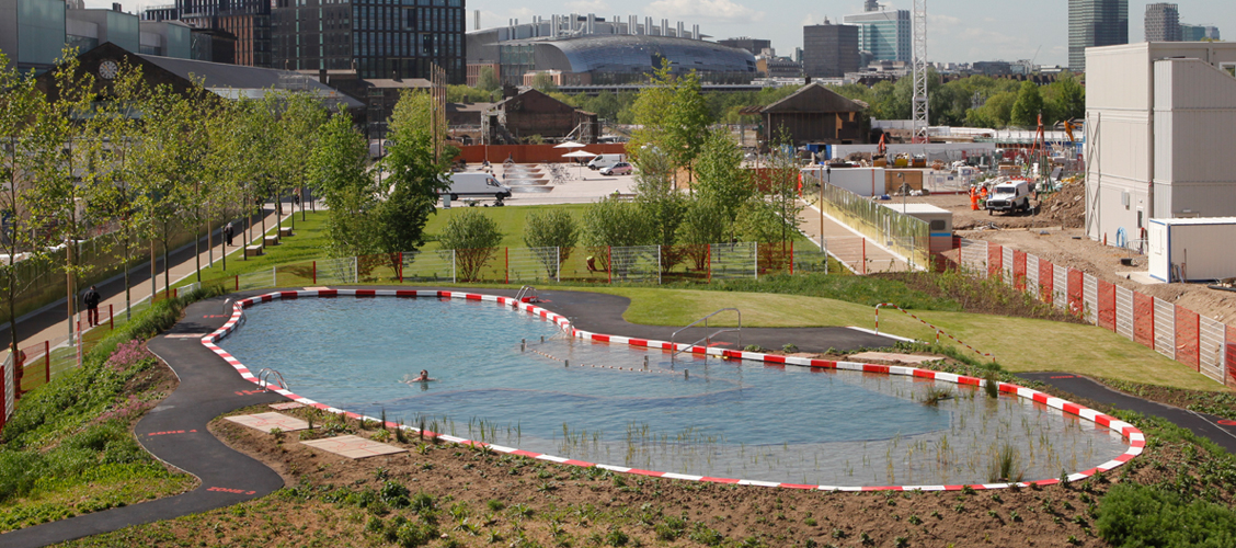
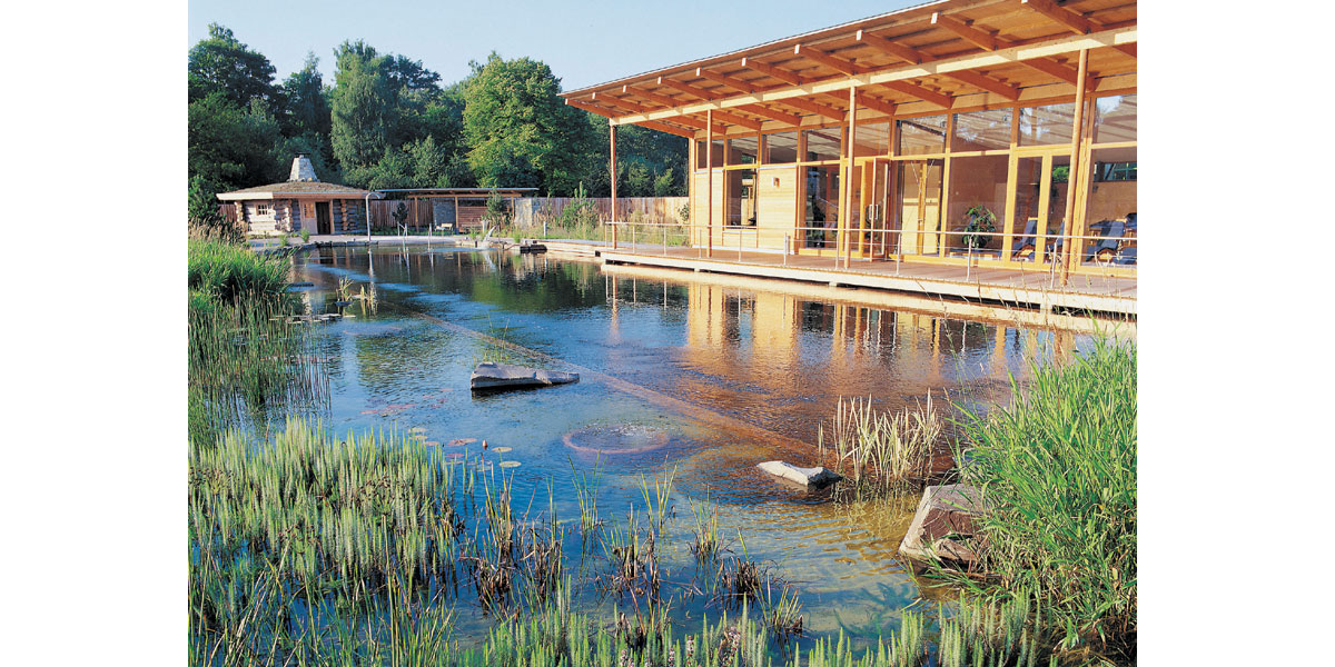
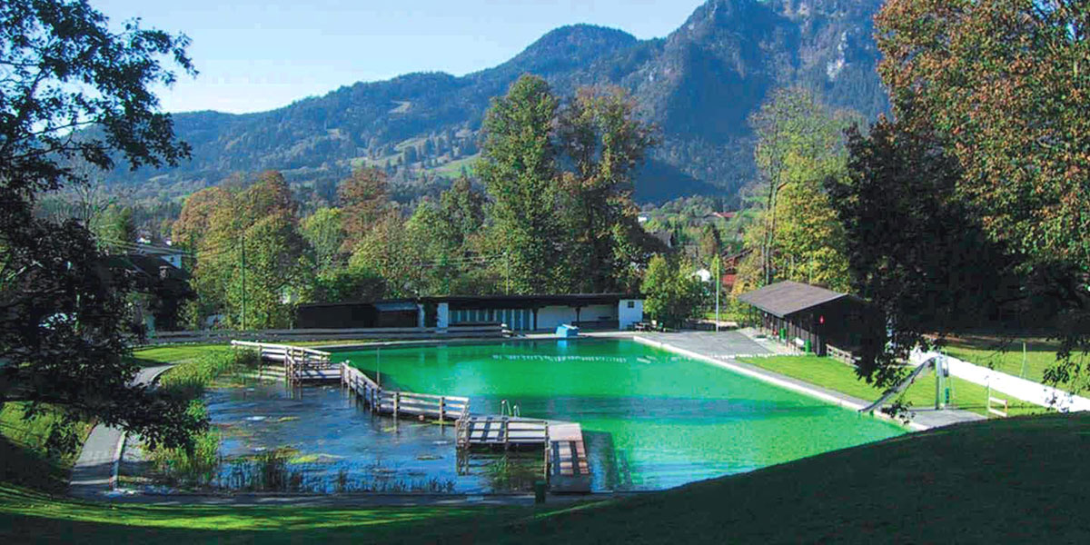
Other companies make natural swimming ponds as well, and it is the easiest way to show the vast variety. Click on the image to jump to the site.
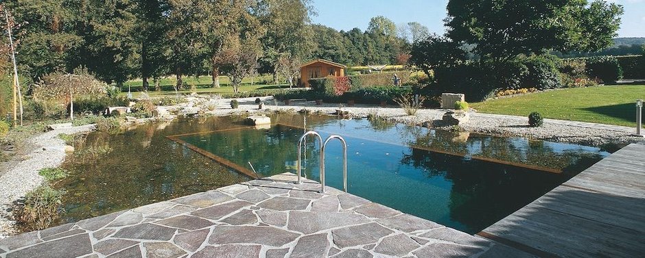
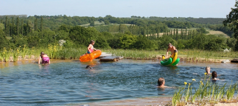
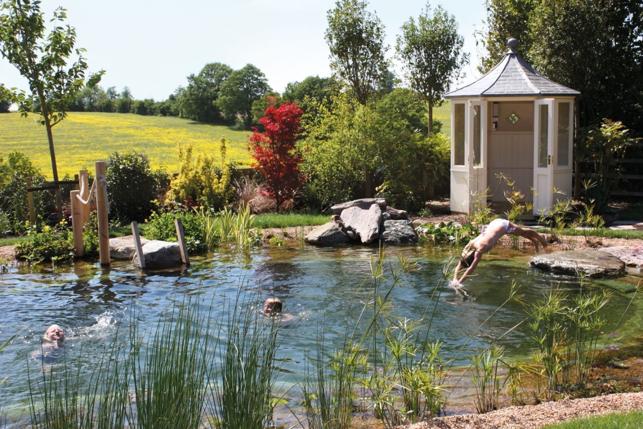
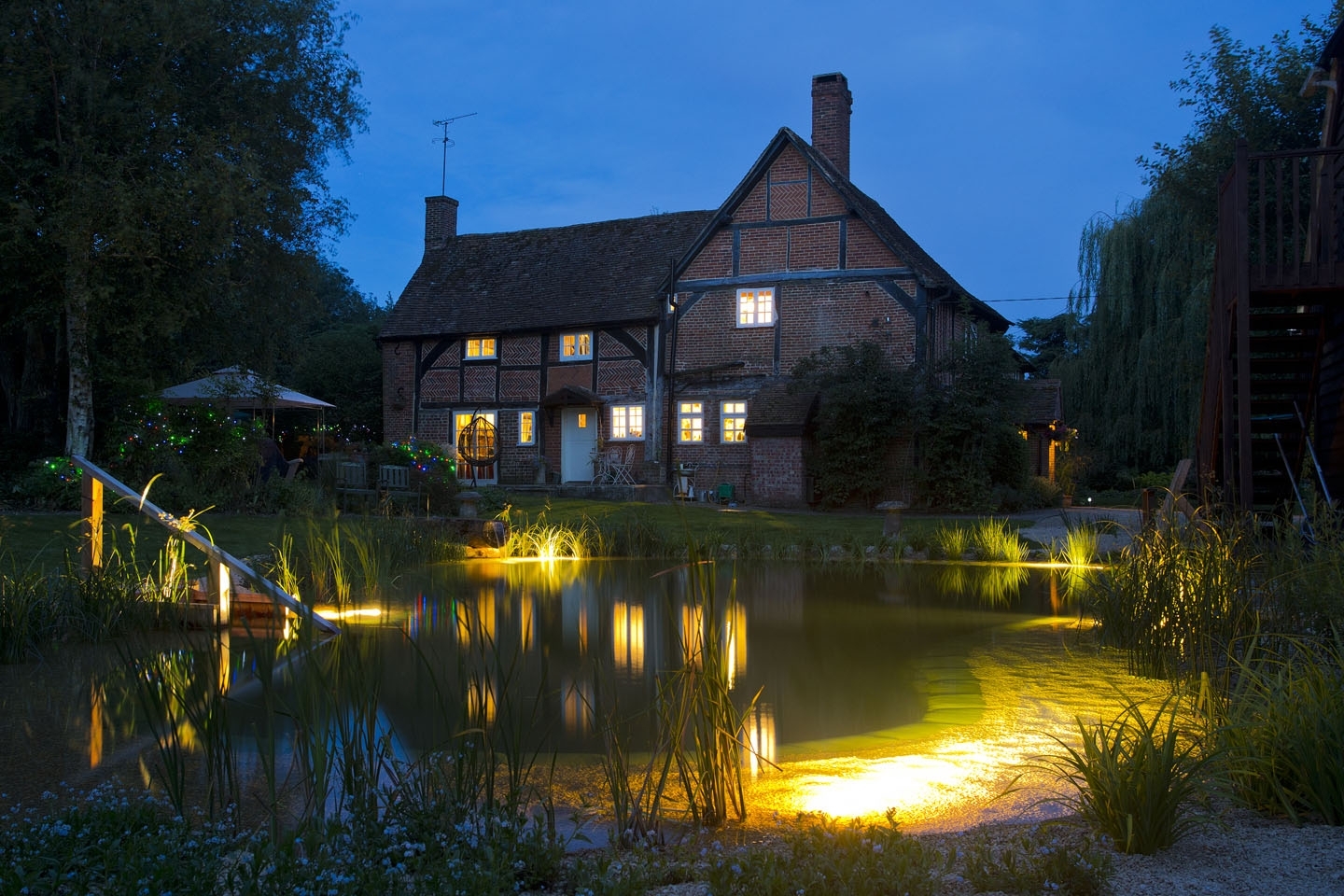
There are many more examples to search for. If we had the space it would be an attractive option to consider.
The concept of keeping the water clean by using nature is similar to the reed beds we use in our water harvesting.
It is nothing new to have water in the centre of our communities. Either rivers or streams and often the village pond. The village pond could be natural or artificially formed by slowing a stream. There are old photos of children and animals using the village pond in several ways. Farms would also frequently have ponds, or duck ponds.
Having a Natural Swimming Pond seems a very good choice given the required space. The water harvesting could be integrated into the system and provide the top up necessary to replace naturally lost water in the pond. The pond could also be the storage for the water harvesting. The make a good fit.
They can also be more formal, with or without planting, but the later is moving away from the concept, but still without chemicals. They can be heated up to about 30o C using air or ground source heat pumps. They can be indoors or form public pools.
Go back to the top of this tab in this section
Go to the next tab in this section
Control the heating
Control the heating
Reduce energy usage by better control of heating and hot water.
This is one article but it could easily be three as there were three changes to the heating and hot water control system, over an extended period of time. Hence it is chronologically incorrect as it should be interspersed with later actions.
The first stage is to move from weekday and weekend control to an everyday controller. This allowed greater flexibility and controls to match our lifestyle at the time.
The next is to install a Tado smart geofenced control for the heating only.
The third stage is to change the smart system to Nest which includes hot water control, but not the same level of geofencing.

Control the heating to reduce bills and carbon
When we moved into this house, the central heating and domestic hot water were controlled by a traditional programmer. A great improvement to either leaving the whole system on all the time, just controlled by thermostats, or a manual switch, akin to lighting a fire in the hearth when you get home. There is an uncomfortable period of being cold before the room or house warms up.
The programmer had settings for Weekdays, and Weekends. An acl Lifestyle (Drayton) Model LP522. We swapped that out for a similar one, but with the additional function of being able to set each day separately. It was a very easy task as the industry had adopted a standard docking for such things many years before. It was just a case of switching off the power supply, unscrew the retaining screws, clip out from the dock and then clip in the new one, and reverse the procedure. Then set the times you want the heating to come one and the time for the hot water, for each day, and sit back and enjoy being comfortable.
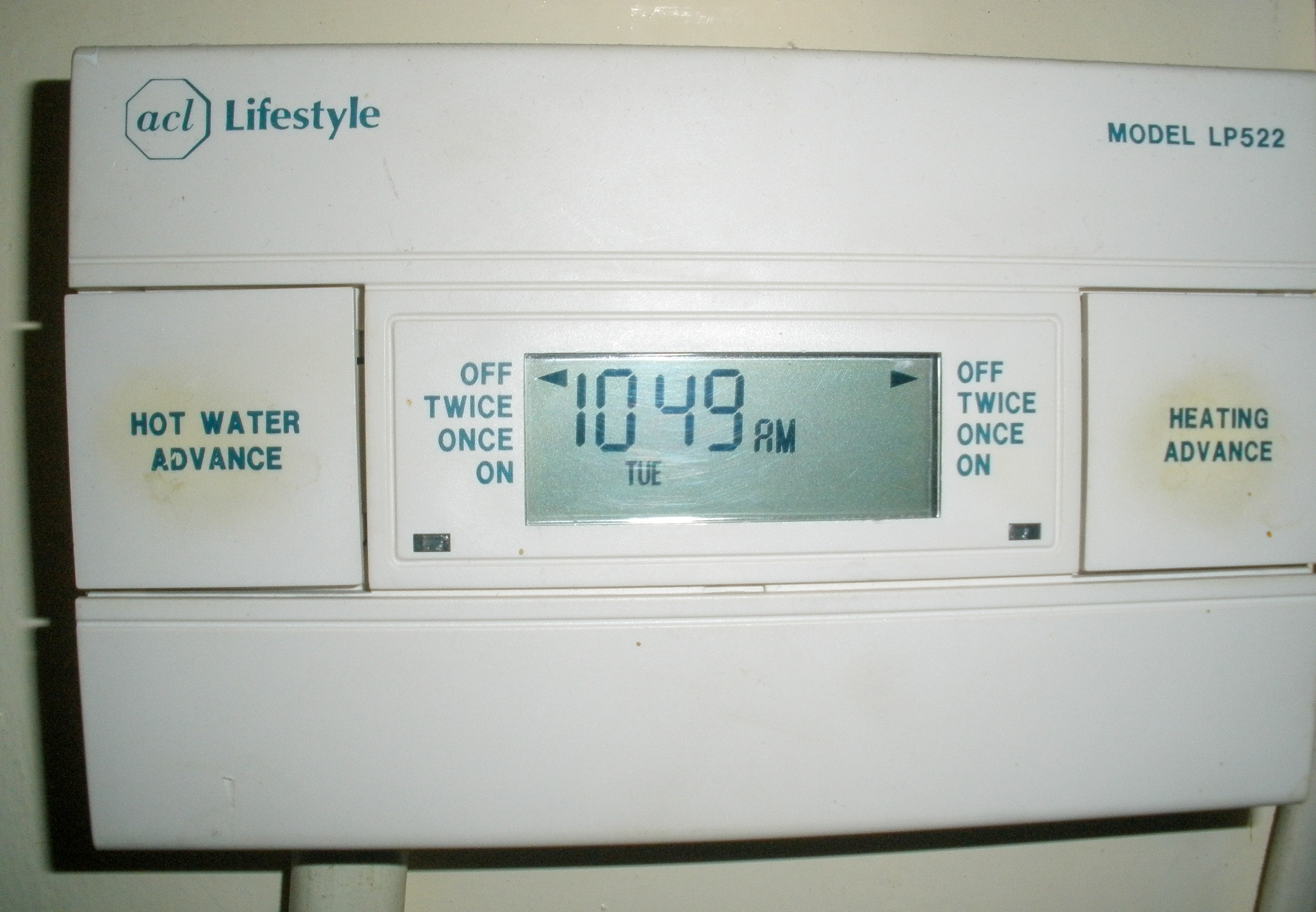 acl Lifestyle (Drayton) Model LP522 Central Heating ProgrammerYou have to guess how long it will take to warm your home to the desired temperature, and add that to the start time whist deciding the settings to apply. In all probability, the only time you would think to change the settings was if you came home and the house was not as warm as you wanted it, so you would start the heating earlier. Another time to consider changing the settings was if your work patterns changed, resulting in different times of occupancy. Obliviously, the settings are dependant on the occupancy of the house by anyone in the household.
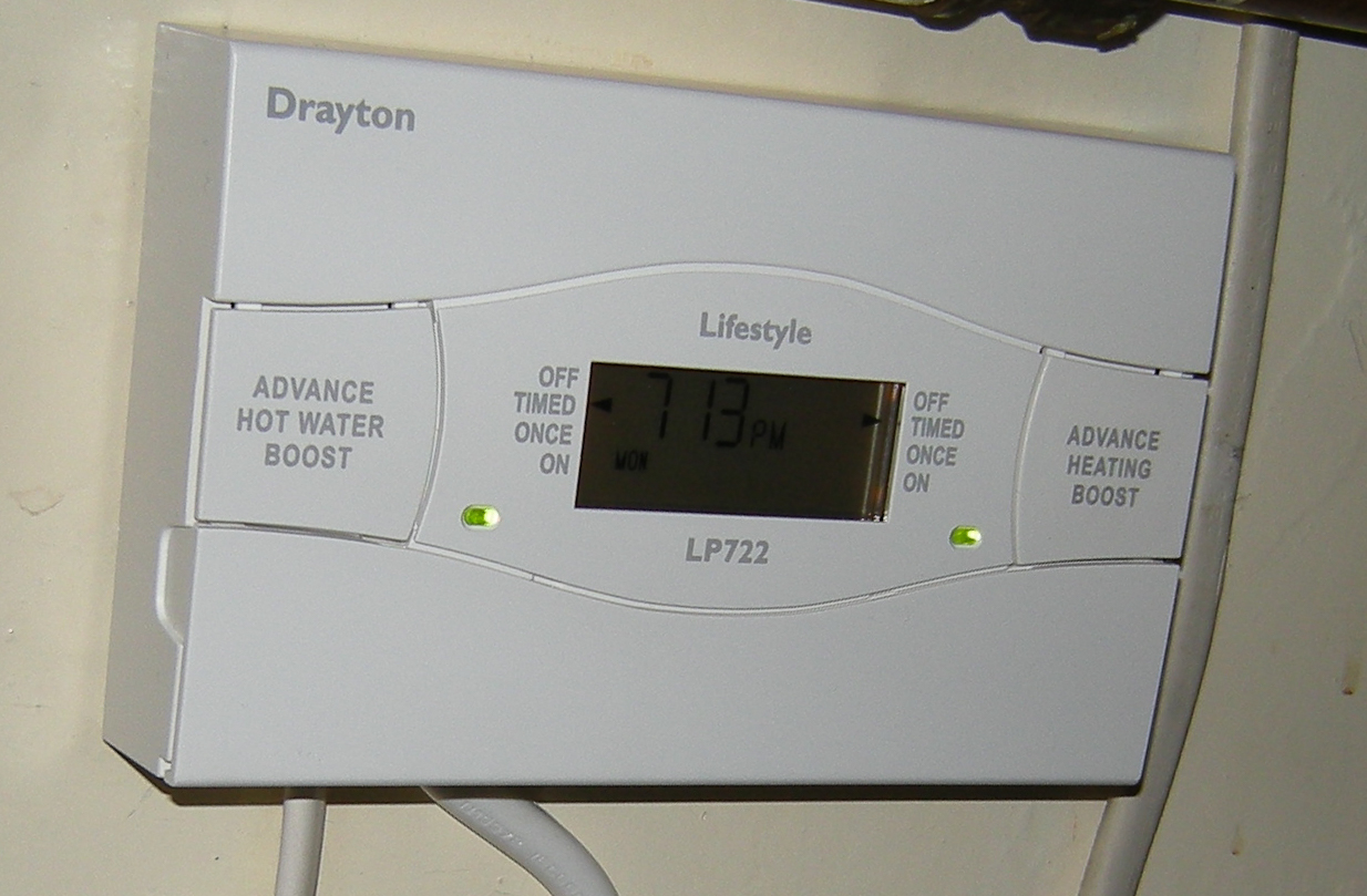
You can see from the photos that the replacement, a Drayton Lifestyle LP722, is very similar to the one it replaced.
The technology was not changed between one unit and the other, just the functionality of each day programming.
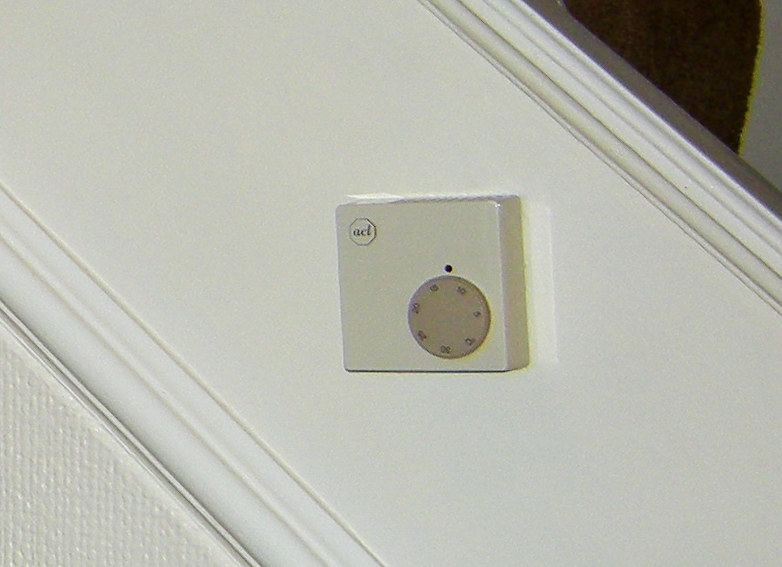
The wiring of the system is the ultimate logic control. Ours is the S Plan wiring with two valves, one for central heating and the other for hot water. The hot water is called on by a thermostat on the cylinder. The central heating is called on by a room thermostat, in our case, in the hall, mounted on the stairs. It is hard wired to the Junction box containing the S Plan wiring.
Smart Controls
I had been investigating and watching the development of smart controls for some time at this point.
Multiple sensors both inside and out measure the temperatures. Combined with learning the thermal mass of the house and it's heating characteristics.
This was the early days of development by small British companies, and came with the not unexpected large price tag to accompany it.
By memory, slightly vague, only, one of the developers was bought by Honeywell. I currently have no evidence that this happened, but it is not unusual for development companies to be bought up by larger more established companies. This also happened with Nest being bought by Google.
The sensors allow for changing the the time to start the boiler, based on a combination of the outside temperature and the learnt heating characteristics of your home. This improves efficiency and reduces bills, as well as improving the probability of walking into a comfortable home. The unexpected cold snap is catered for by starting heating earlier than the time set to reach comfort level. Conversely, if warmer, it delays the start, avoiding using energy unnecessarily, thereby saving money and carbon.
The advent and proliferation of Smart Phones and GPS together with other technical advances, including increasing broadband speeds and availability, provided another step change in the control of heating. Instead of having sensors to detect outside temperatures the connected controller could use the internet to get data regarding forecast weather and current temperatures in your area. Also, your phone knew were you were, and could therefore automatically tell your heating controller. The further away from home your are the more time your system has to get to the comfortable walk through the door. As you start to come home your phone's GPS system tells your heating controller that you are on your way. The smart heating controller has learnt how long this journey normally takes and therefore adjusts the start time accordingly. It is not inconceivable to use other data, both learnt and real time to check your predicted journey time. It could use the car's GPS to tell if you are travelling in your car, or other data, for public transport. However, I don't know that they do that yet, using the Internet of Things, along with other data. It is surprising how much joined up intelligence there can be in the background.
I am not suggesting that it does or should do any of the following. Your car's GPS states that it is on the drive. Alternativly, perhaps somebody else is driving it. The seat position may help identify who, but a correlation of speed and direction of the car and a mobile phone will identify the probable driver. You on the other had are at the railway station, you have bought a coffee and paid using a contactless payment system. The retailer has a location, in the station. You have gone through the barrier and your ticket is activated, perhaps even on your phone. The CCTV cameras facial recognition confirm that it is you. The phone's GPS confirms you are in these locations. But wait, you are inside and can't be seen by the GPS Satellites. The station has an internal GPS system developed to help passengers find their pre-booked seats, by following instructions on their smart phones, which has the train ticket. You get on the train, your phone knows which platform and which carriage. Real Time train information can correlate this to the service and the predicted journey times. The speed, route, and stopping pattern obtained from you phone's location can be compared against the planed data and that of the real time information. The prediction of the need for comfortable heat is now accurate to within minutes. The system has learn how long it takes you to get from the home station to your house, however, it cannot predict the non habitual visit to the pub, or to the florist to buy flowers, but both of those are outwith the range to make any difference to the heating call.
Having all the other factors of weather and current temperature to hand, the system can fully optimise the heating up cycle of the system. Inside, there are other monitors of occupancy, which if indicating an empty house, perhaps with the phone left behind, can lead to the heating being switched off. There are plenty of ways to monitor occupancy these days, including the smoke and carbon monoxide detectors, the intruder alarm, and even the wi-fi router.
An article from 2011, 'What is a Smart Building'. Another from 2019. 'The rise of the smart home'. 'Smart thermostats provide several advantages over their traditional counterparts, but there are two main benefits. They are easier to programme and use, and they give greater energy savings. Average gas bills in the UK are £676 a year, and Tado, the smart-thermostat manufacturer, estimates UK customers can save 19% on heating bills. Nest claims that UK customers can save between 8.4% and 16.5%. '
Tado
Our next investment in Heating Controls was a Tado Smart Thermostat. Not the version in the link, but similar. The wired version directly replaced the pervious one in the hall and the other object provides internet connection.
Tado Smart Thermostat
The Tado Smart Thermostat was easy to install in the same place with no additional wiring. The thermostat only controls the heating side and not the domestic hot water, but it is more than just a thermostat. It is also the programmer as it controls the schedule or timings via an App. Accordingly the existing programmer, was turned to always on for central heating, relinquishing control to the Tado Smart Thermostat and App, and the hot water remained with the previous arrangement of programmer and cylinder thermostat.
Tado does now have a hot water controller as well as the central heating.
Tado has Geofencing, whereas Nest for instance relies on you using an App on your phone to alert it if you are going to be home early or late. Tado interfaces with your phone to assess this automatically.
The Tado App does a lot more than it used to.
However, our family work patterns changed, making Geofencing less of an advantage and Tado changed it's pricing model from a fixed purchase price, including all of the data interfaces, to a hardware price plus subscription.
Accordingly we changed to Nest.
Nest
Nest is also a Smart Thermostat and describes itself as a Learning Thermostat. It does not have the same Geofencing as Tado but integrates well with our Nest smoke and carbon monoxide detectors. which include motion detectors. Both Tado and Nest integrate with Google Home, our choice of Smart Home engine. However, I am not sure if Tado was so enabled when we switched over. Apparently that link happened in 2017.
Google acquired the company for $3.2 billion in January 2014. However, it was not fully integrated until 2018. Snice that time some of the functionality of the Nest products have been lost and I think added security has put significant delays into notifications from the Nest Doorbell and cameras. It is still quick enough to capture nefarious activities, but not as quick as the postman or delivery driver may like. Nest smoke and carbon monoxide detectors used to be able to interface with Philips Hue lights and turn colour enabled Smart LED lights red at the time of an alarm, making the alarm useful for both the visually and hearing impaired person. Nest Learning Thermostat
Nest does control the hot water in the one App and connects wirelessly to the system so it is easy to move the thermostat to the most convenient location for you, rather than the wires.
Nest is easy to set up and operate. The predicted savings may be less than that of Tado but some of Tado's savings will be based on not heating an empty home.
The family dynamic has changed again, as we are both retired now. Heating predictions are not as relevant in terms of creating savings of money, energy, and carbon. Technology has also moved on.
Watch this place for the next chapter.
Go back to the top of this tab in this section
Go to the next tab in this section
Draft proofing and partial internal insulation
Draft proofing and partial internal insulation in the Bathroom
Draft proofing and partial internal insulation
The next project was to do with the bathroom. It was cold and draughty. Some of the tiles above the bath had popped and allowed water from the shower to flow where it was not wanted. A temporary repair had been done, but it was not ideal. Also, David is tall, and the roof is sloping. Time for a change. Reduce the drafts, insulate, and move the bath shower into the room to increase the height.
 Water being drained down from the bidet tap and David commencing disconnection of the bath waste
The bidet had to go to make space for the bath to move into the room. Adding 100mm of insulation to the external wall would reduce the room size of an already small bathroom, but the benefits were worth the loss.
The progress of the works can be seen in the slideshow below.
Once the bath was removed it was apparent why it was so cold and draughty. The holes through the wall to the outside for the waste pipes were not sealed. The wall below the bath rim was not finished or plastered. The floor had a significant gap, albeit for services.
The holes were sealed and the wall insulated with 100mm PIR and an air gap between the insulation and the Aquapanel waterproof board. The flat substrate for a good tiled finish.
Go back to the top of this tab in this section
Go to the next tab in this section
Composting and wormery
Composting and wormery
Your text...
Composting and wormery
Go back to the top of this tab in this section
Go to the next tab in this section
Energy saving bulbs
Energy saving bulbs
Your text...
Energy saving bulbs
Go back to the top of this tab in this section
Go to the next tab in this section
Nest Smoke Alarms
Nest Smoke Alarms
Your text...
Nest Smoke Alarms
Go back to the top of this tab in this section
Go to the next tab in this section
Philips hue
Philips hue
Your text...
Go back to the top of this tab in this section
Go to the next tab in this section
Smart home
Smart home
Your text...
Smart home
Go back to the top of this tab in this section
Go to the next tab in this section
Temperature sensors
Temperature sensors
Your text...
Temperature sensors
Go back to the top of this tab in this section
Go to the next tab in this section
Smart meter
Smart meter
Your text...
Smart meter
Go back to the top of this tab in this section
Go to the next tab in this section
Roof
Roof
Your text...
Roof
Go back to the top of this tab in this section
Go to the next tab in this section
Solar PV and Battery
Solar PV and Battery
Your text...
Solar PV and Battery
Go back to the top of this tab in this section
Go to the next tab in this section
Loft insulation
Loft insulation
Your text...
Loft insulation
Go back to the top of this tab in this section
Go to the next tab in this section
Additional rainwater harvesting
Additional storage capacity for rainwater harvesting
We have two narrow water butts at the front of the house. They help with watering the many pots there. We have capture on one of the downpipes at the back garden, which diverts into the reed beds. Another capture point is from an outbuilding to a normal size water butt and onto a cistern planted with native water lilies.
However, these water butts are on a different scale.
Environmental impact is again reducing the power consumption at the water treatment plant it would otherwise go to. In addition to that, in a very very small way, it reduces the likelihood of flooding further downstream by absorbing some of the surge. Not one or two on their own, but in sufficient numbers! We noticed one being delivered to a neighbour recently. Every little helps.
Additional rainwater harvesting
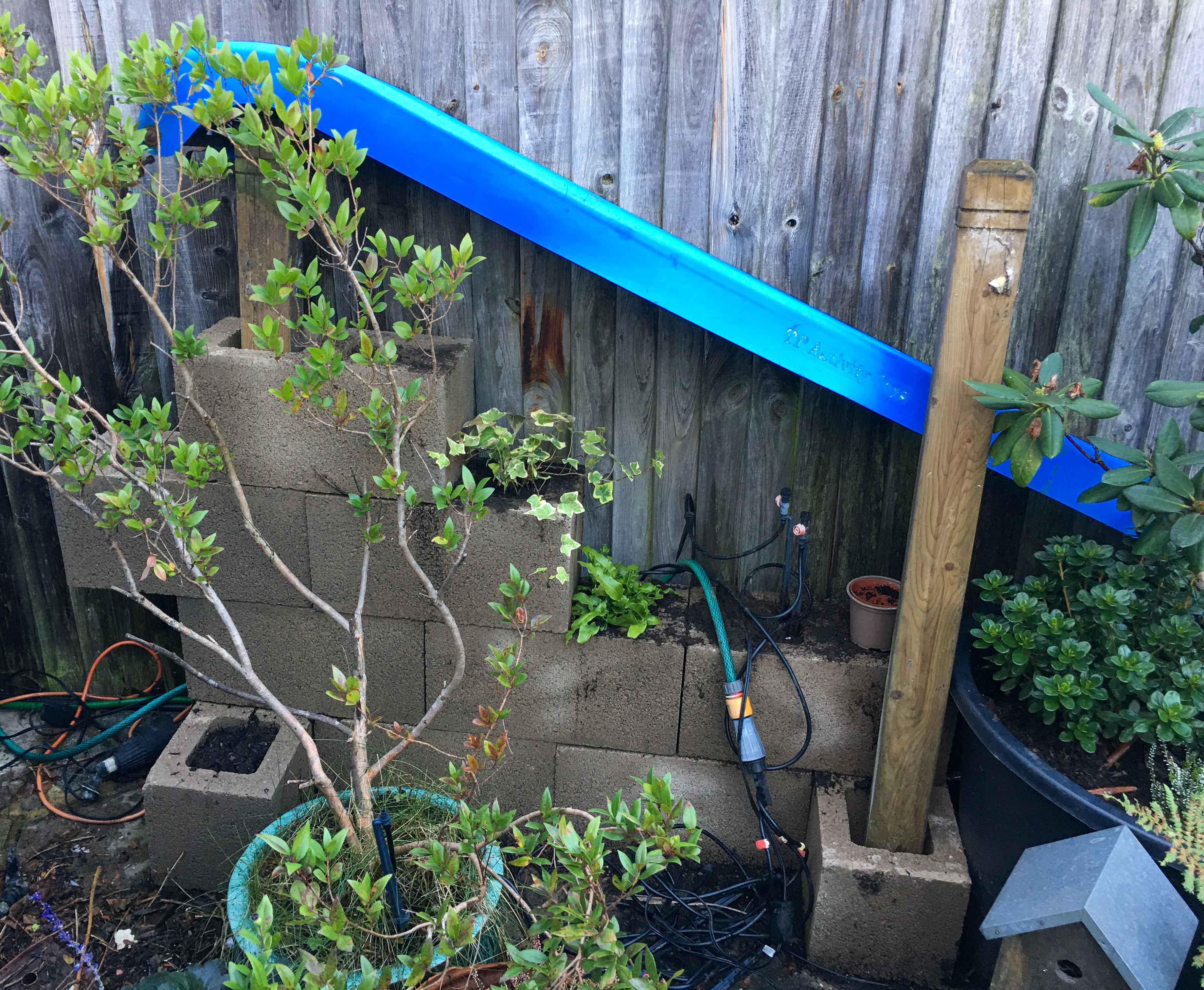
The additional capacity is provided by two 800 litres water buts from Ecosure. The two water buts will be linked together to form a 1600 litres or 422 gal. storage. The rainwater does not need to be processed by the reed bed to make it useable, unlike the greywater. This arrangement will therefore reduce the electricity requirement to pump water from the reed bed to storage. Apart that is for any overflow water. The overflow from the new water butts will outfall onto David's old slide, repurposed into a water course, which will then flow into the reed bed.
Go back to the top of this tab in this section
Go to the next tab in this section